Ribbon
Introduction to SWE Edge & CNe Edge
The SBC SWe Edge is virtualized SBC software that can be deployed on Commercial Off-the-Shelf (COTS) Intel® x86 hardware platform running KVM, VMware® ESXi, and Microsoft Hyper-V hypervisors. It can also be deployed in public cloud environments including Microsoft Azure and AWS.
The Ribbon SBC Cloud Native edition Edge (CNe Edge) is a public cloud-based enterprise SBC. The CNe Edge breaks the main SBC SWe Edge functions into separate services: the media and the signalling. This enables increased session density and support resiliency. The SBC CNe Edge node is based on Kubernetes orchestration and initially available in Microsoft Azure Kubernetes Service (AKS) in a cluster.
This configuration guide describes how to set up Ribbon SWE Edge or CNe Edge SBCs to interwork with DIDWW Voice IN/OUT SIP trunk services.
Getting started
What you need to get started:
Ribbon inbound voice trunk configuration
Enter the public IP address of the SBC or the FQDN/DNS name and login with your username and password (Fig. 1).
Fig. 1. Ribbon SBC login page.
After login, navigate to Tasks -> SBC Easy Setup -> Easy Config Wizard (Fig. 2).
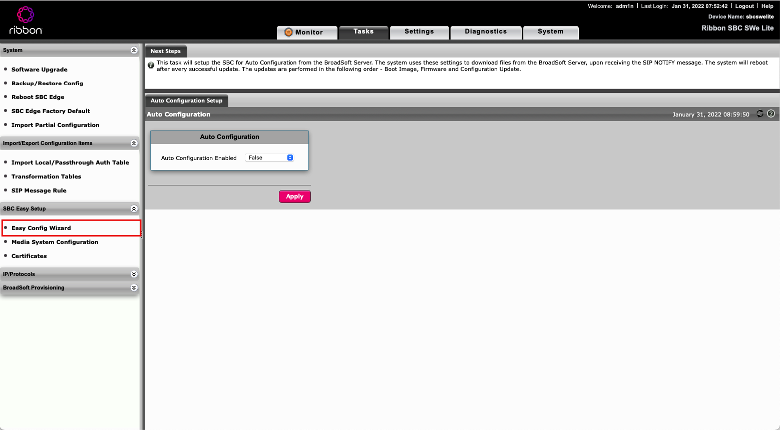
Fig. 2. Ribbon SBC interface.
Step 1:
Select “SIP Trunk” for your application (Fig. 3).
Enter scenario description e.g. “DIDWW Inbound”
Select the “Telephone Country”
Enter the number of maximum allowed concurrent SIP sessions
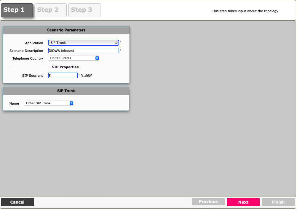
Fig. 3. Easy Config Wizard.
Step 2:
Enter DIDWW IP, protocol and port information (Fig. 4).
DIDWW New York IP is used in this example.
Border Element Server – 46.19.209.14
Protocol - UDP
Port Number - 5060
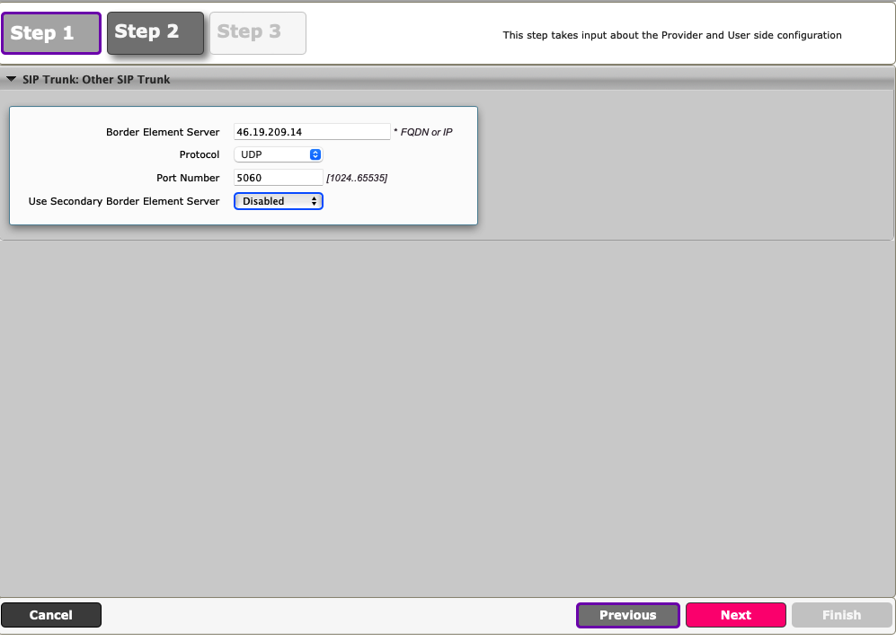
Fig. 4. Inbound SIP trunk details.
Step 3:
Confirm the details and click Finish to save the config.
Step 4:
Navigate to Settings -> Signalling Groups and click DIDWW Inbound: Border Element
Add inbound signalling IPs into the Ribbon SBC, as shown in the example below (Fig. 5).
A full list of DIDWW inbound signalling IPs:
46.19.209.14:5060 (for New York POP)
46.19.210.14:5060 (for Frankfurt POP)
46.19.212.14:5060 (for Los Angeles POP)
46.19.213.14:5060 (for Miami POP)
46.19.214.14:5060 (for Singapore POP)
46.19.215.14:5060 (for Hong Kong PoP)
185.238.173.14:5060 (for Amsterdam PoP)
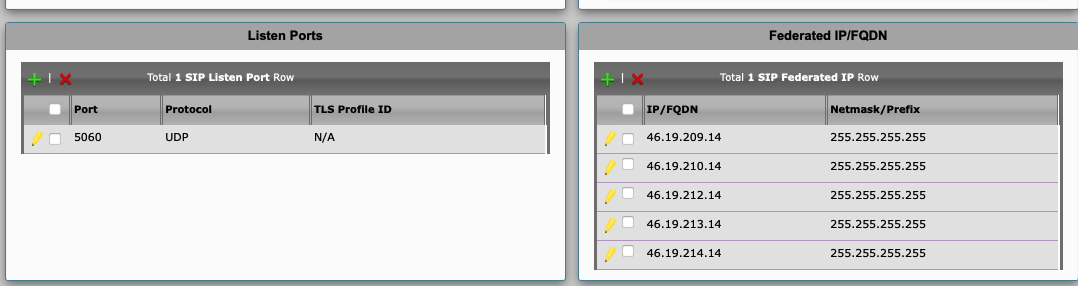
Fig. 5. Allowing DIDWW signalling IPs.
Step 5:
Navigate to Settings -> SIP -> SIP Server Tables and click DIDWW Inbound: Border Element
Select SIP Options as shown in the example below (Fig. 6).
Enter any preferred Local and Peer usernames
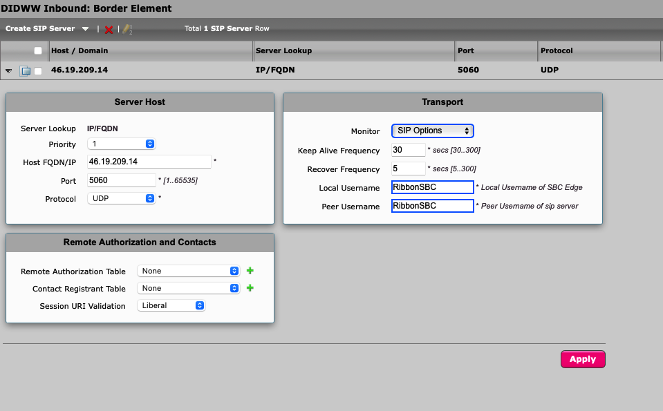
Fig. 6. Enabling SIP options.
Ribbon outbound voice trunk configuration
Navigate to Tasks -> SBC Easy Setup -> Easy Config Wizard (Fig. 1).
Step 1:
Select “SIP Trunk” for your application
Enter scenario description e.g. “DIDWW Outbound”
Select the “Telephone Country”
Enter the number of maximum allowed concurrent SIP sessions
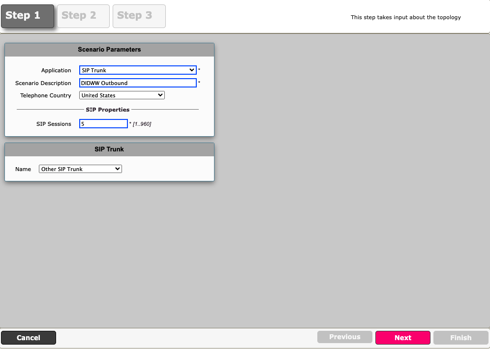
Fig. 1. Easy Config Wizard.
Step 2:
Enter DIDWW FQDN, protocol and port information (Fig. 2).
Select the preferred DIDWW outbound FQDN from the list below:
nyc.us.out.didww.com
fra.eu.out.didww.com
lac.us.out.didww.com
mia.us.out.didww.com
sg.out.didww.com
DIDWW New York FQDN is used in the following example
Border Element Server – nyc.us.out.didww.com
Protocol - UDP
Port Number - 5060
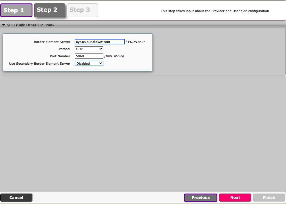
Fig. 2. Outbound SIP trunk details.
Step 3:
Confirm the details and click Finish to save the config.
Step 4:
Navigate to Settings -> SIP -> Remote Authorization Table and click on Create Remote Authorization Table (Fig. 3).
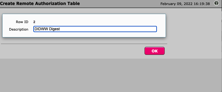
Fig. 3. Creating Remote Authorization Table.
Step 5:
Select the created authorization table and click on Create Remote Authorization Entry (Fig. 4).
Realm - out.didww.com
Authentication ID - Outbound Trunk Username
Password - Outbound Trunk Password
Confirm Password - Outbound Trunk Password
From URI User Match - Regex
Match Regex - (.*)
This RegEx expression means “Everything”.
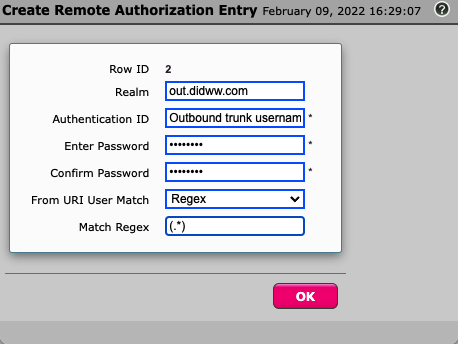
Fig. 4. Creating Remote Authorization Entry.
Step 6:
Navigate to Settings -> SIP -> SIP Server Tables and click on DIDWW Outbound: Border Element
Add DIDWW Digest Remote Authorization table.
Configure SIP Options as shown in the example below (Fig. 5).
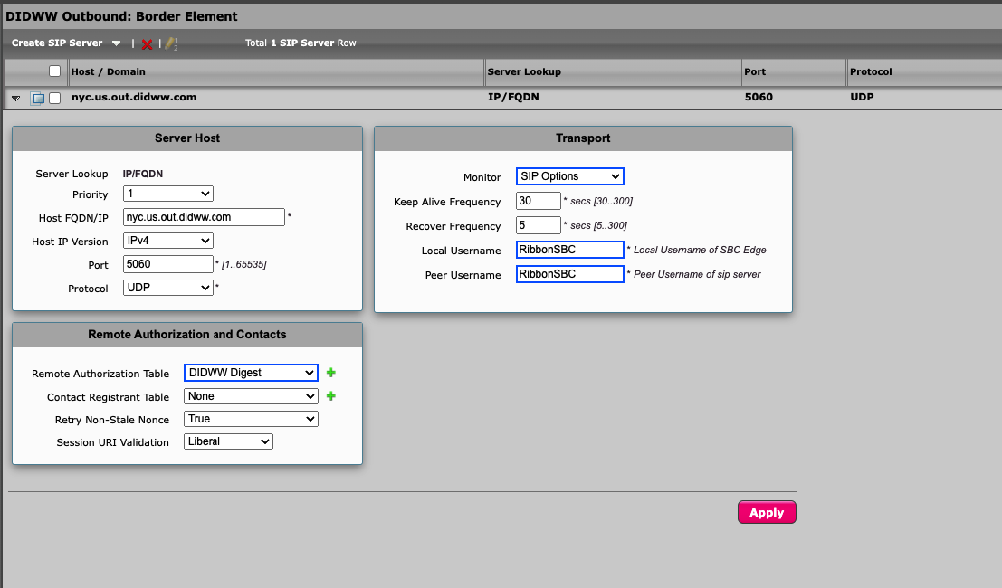
Fig. 5. DIDWW Outbound SIP server table configuration.
Step 7:
Navigate to Settings -> Call Routing Table -> DIDWW Outbound : From SIP Trunk and click Create Call Routing Entry
Under Destination Signalling Groups -> Add DIDWW Outbound: Border Element (Fig. 6).
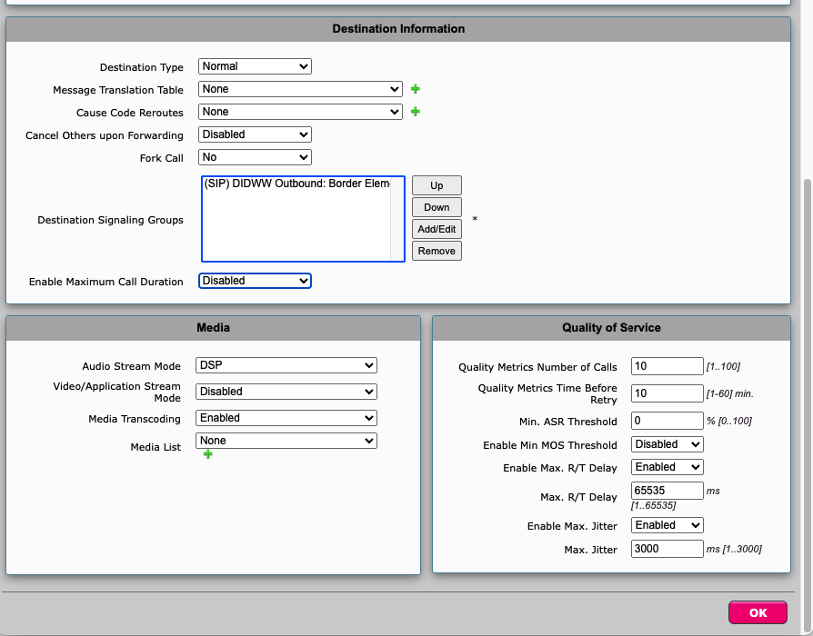
Fig. 6. Creating Call Route Entry.
SIP connectivity
After successfully configuring both trunks, the “Service Status” should be displayed as Up (Fig. 1).
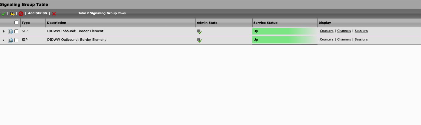
Fig. 1. SIP connection status.
To check detailed SIP connectivity status of your Signaling Group, click Counters (Fig. 2). You should see SIP options pings in the Outgoing tab as well as 200OK responses in the Incoming tab.
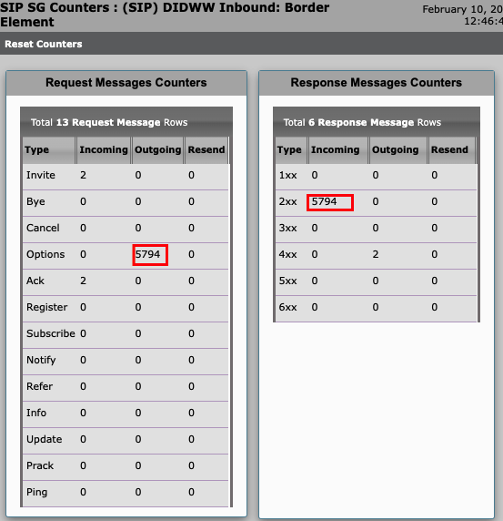
Fig. 2. SIP Message Counters.
To confirm that the outbound trunk setup was successful, simply make a test call using Ribbon test calling tool (Fig. 3).
Navigate to -> Diagnostics -> Tools -> Test A Call
Destination Number - enter destination number
Origination/Calling Number - enter originating number
Call Routing Table - DIDWW Outbound: From SIP Trunk
A green checkmark indicates a successful completion of a test call.
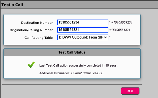
Fig. 3. Test Call Tool.
Troubleshooting
Ribbon provides a Packet Capture feature for troubleshooting (Fig. 1). This option is used to identify and better understand SIP signalling issues.
To start capturing packets:
In the Ribbon web interface, click the Diagnostics tab.
In the navigation bar, select Ribbon Service Troubleshooting > Packet Capture.
Click Start Capture.
Select the network interface (including IP version) from which the packets will be captured.
Select protocols to capture the packets.
Configure any relevant information in the Other Options section.
Click OK.
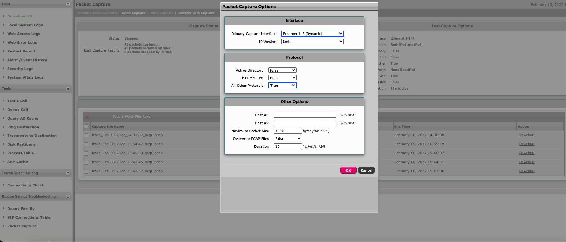
Fig. 1. Starting packet capture.
Once the packet capture is complete, simply open the PCAP file with Wireshark for a full analysis of the SIP Signalling stream (Fig. 2).
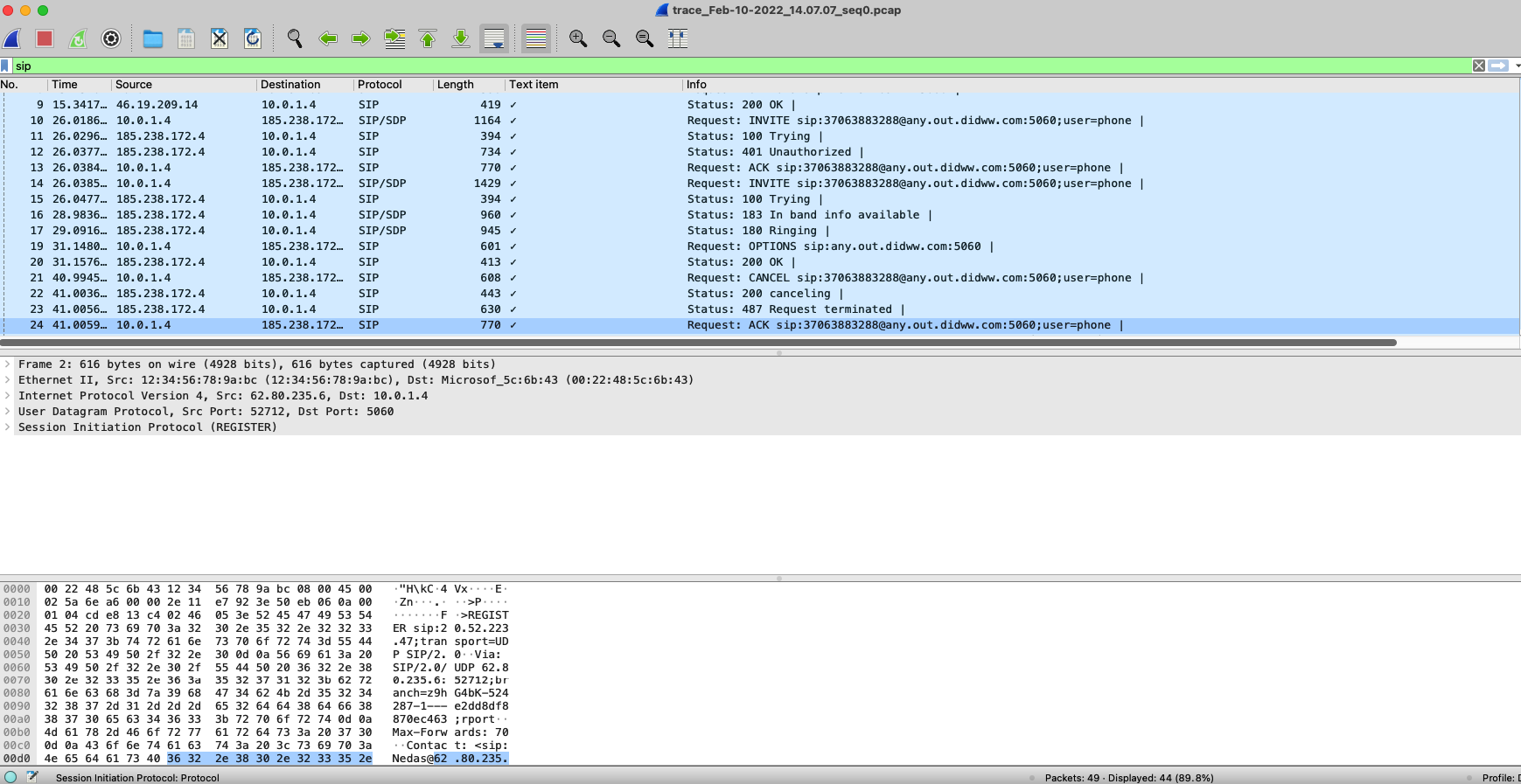
Fig. 2. SIP signalling stream via Wireshark.